RF Grounding is not the same as electrical grounding although they function the same way so we’ll discuss them in the same manner for practical reasons. Grounding is needed in order to protect expensive electronic equipment, like radio transceivers, and sometimes the operator from being damaged by excess current introduced into a system. This current can come from the antenna, from a lightening strike and from static build-up among other sources. Since current likes to follow the path of least impedance back to the Earth, we can understand grounding as an emergency overflow valve for electricity that provides the shortest, easiest path back to the Earth.
For electrical safety, simply grounding your power supply will be enough but to protect your other radio equipment each piece should be individually grounded.
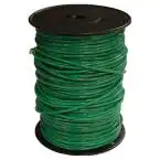
To ground a piece of equipment, attach a copper wire to each device’s ground connection. It’s commonly labelled GRD, GRND or GROUND. If there’s no such connection point labelled then consult the manufacturer’s documentation. Then run that wire to a grounding rod that’s been driven into the ground. Your goal here should be to keep the wire as short as possible.
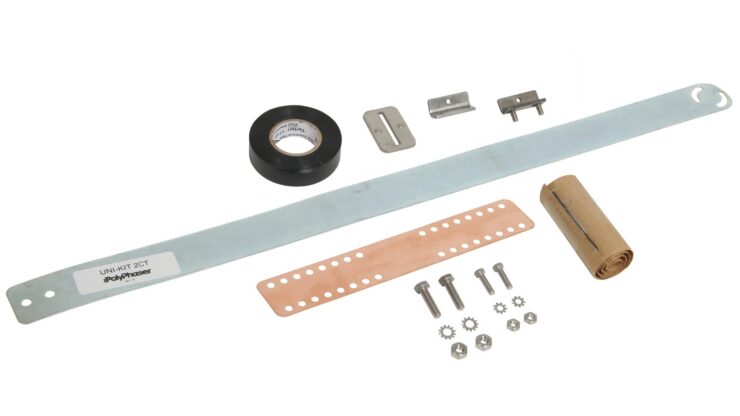
Instead of using a wire to connect your equipment to grounding rod, the best practice is to use a flat copper strap. Straps are preferred over wires because RF current flows over the surface of conductors, so a connection with more surface area will reduce impedance and increase grounding performance. Just like with wire, you want to minimize the length of your strap.
When grounding multiple pieces of equipment you should never daisy-chain equipment grounds together. That is, you should never connect the ground on one piece of equipment to another piece of equipment. Instead, all the grounds should be connected to a common bus. In this case, a bus is simply a shared conductor that all grounds attach to. Then the bus is attached to a copper strap which runs to your grounding rod.
Grounding rods should be made of copper and be about 8ft long. Drive your grounding rod deep into the ground so only a minimal amount is above ground. Then bond your copper strap to it.
You should also install a lightening arrestor between your antenna and your radio equipment.
Generally anything with a metal case should be grounded and ALL wires should be kept as short as possible.
So, a typical grounding setup will involve a lightening arrestor, copper strap, grounding rod, wires and bus. A grounding wire will run from each piece of equipment to the bus where it’s been bonded. Then the bus will be bonded to the copper strap which runs to the grounding rod. The rod is bonded to the strap and driven into the ground. All wires and straps are kept as short as possible. A lightening arrestor is similarly installed between the antenna and the radio and similarly grounded correctly according to manufacturer instructions.
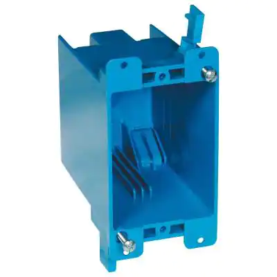
For obvious reasons you want to insulate your grounding system since it’s a conductor carrying both a charge and generating heat. If you’re running it inside of a house you will want to use electrical boxes and conduit to protect both your home and curious hands for burns and accidental discharge.
Multiple Ground Rods
As much as possible, for short runs under 60ft or so, avoid having multiple ground rods. When you have multiple paths to ground you can create an electrical loop. If you do have multiple ground rods, make sure they are bonded (electrically connected) to each other with a larger gauge non-stranded wire than everything connected to them.
How I grounded my radios
First, I ran 10 AWG solid, non-stranded copper wire (insulated and green to indicate ground) from my grounding rod to my radios. I bonded the green ground wire to the grounding rod using a bronze clamp and ran the wire through my crawlspace up through the wall.
In an effort to make it look “nice” I took a 1-gang electrical box and a blank faceplate and installed that inside the wall at the same height as a normal electrical outlet.
I then used a Dremel tool to create a small hole in the faceplate and epoxied a small electrical bus to it. Then I ran the grounding wire through the 1-gang electrical box, through the faceplate and bonded it to the bus that’s epoxied to the faceplate. This gave it a somewhat professional view.

I then mounted a Siemens insulated electrical bus to underside of my desk. Then I ran a short grounding wire from each piece of equipment to the insulated bus. This gave me the potential to connect upto 22 pieces of equipment to the common insulated bus in the future…and mounting it on the underside of the desk prevents it from being bumped and generally just looks nicer.
Lastly, I ran a length of grounding wire from the insulated bus mounted on the underside of my desk to the bus I mounted to the faceplate, creating a complete ground run from each piece of equipment to the a common ground that ran all the way to my house’s ground rod.

I don’t leave my antenna up when I’m not operating and don’t operate in bad weather so I typically don’t bother to ground it…but when I do feel the urge to ground, I run a length of ground wire from my antenna to my common insulated under-desk bus.